
太陽を宿し、夜にモールスを灯す蛍。
Taiyō o yadoshi, yoru ni Mōrusu o tomosu hotaru.
A firefly carrying the sun, lighting Morse in the night.
FireFly Solar is my small solar-powered Morse blinker for outdoors. Think of it as a solar-punk style LED throwie, but without the disposable coin cell.
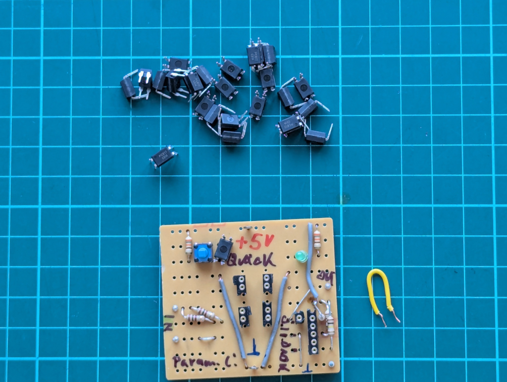
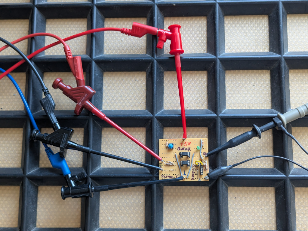
Some years ago, when I started playing with AVR and ATtiny programming, I built a very simple Morse “throwie”: one ATtiny, one LED, one resistor, and some power-friendly firmware. The goal was to use as few parts as possible while still doing something useful.
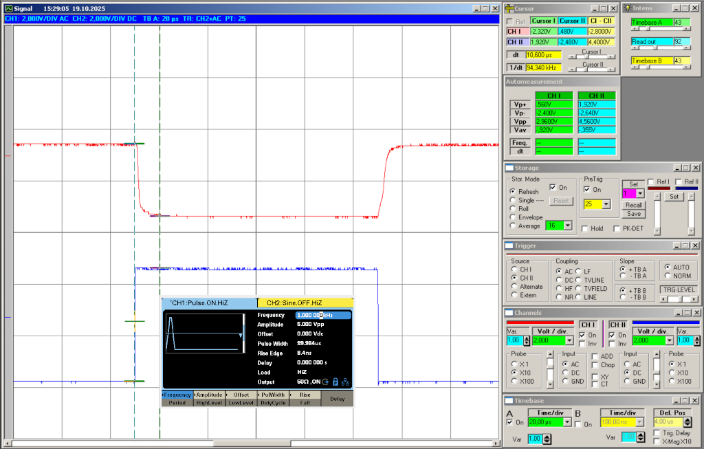
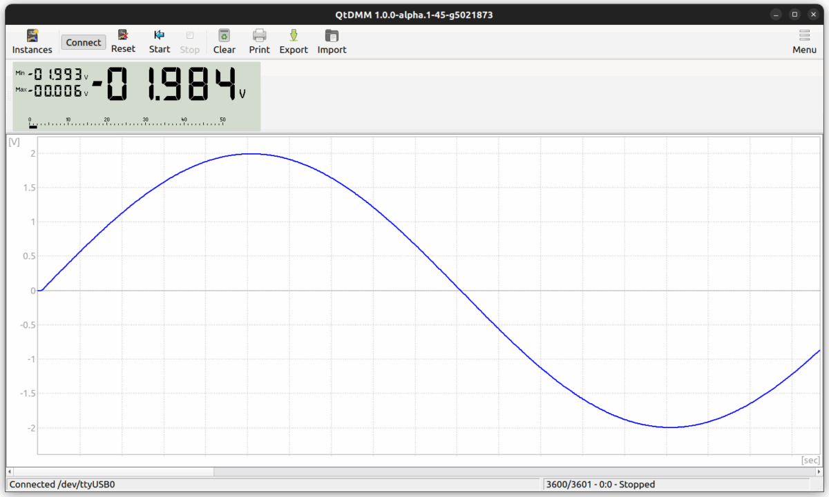
The basic behaviour is simple: detect daylight, sleep when it is bright, blink when it is dark. The LED can even be used as a light sensor, which keeps the hardware nicely minimal.
This new version keeps the spirit of that old project, but moves it closer to a small outdoor object. It uses a solar cell and supercapacitor instead of a disposable battery. During the day it charges. At night it wakes up and sends a Morse-style light signal.
So it is no longer really a throwie. It is more like a small pendant or garden signal creature. Hang it somewhere with daylight, keep the electronics protected from direct weather, and let it blink when the sun is gone.
Why this Name?
Why Japanese? Because I want to do so, but the repository name stays simple: FireFly Solar
For blog posts and documentation I use the Japanese name:
FireFly Solar / 日輪蛍 – Nichirin Hotaru
Roughly translated, this means something like sun-disc firefly. This will keep the solar idea for the new design.
About this Project
This is partly a small hardware project and partly a workflow exercise. I want to improve my practical design skills in a few areas:
- low-power electronics
- solar charging with supercapacitors
- simple outdoor mechanical design
- 3D-printed parts
- documentation for beginner-friendly DIY kits
- repeatable project workflow from idea to small kit
The hardware itself should stay simple. The larger goal is to define a clean path from prototype to PCB, enclosure, documentation, BOM, and maybe a small DIY kit later.
Maybe this will end up on Tindie one day. Maybe it will only become a useful internal reference project for future ToGo-Lab hardware. Both outcomes are fine.
Idea behind
The target is a beginner-friendly soldering kit with clear documentation and hackable firmware.
Current idea:
- MCU: ATtiny45/85, through-hole
- Power: solar cell plus supercapacitor
- Behaviour: night-only Morse-style blink
- Light detection: preferably minimal hardware, using the LED as in the original morse throwie
- Firmware: editable with Arduino IDE
- Mechanics: small outdoor-friendly holder or pendant structure
Where to find the Details
The source files and releases live in the ToGo-Lab Gitea repository, https://gitea.togo-lab.io/tgohle/0001-FireFly
Larger internal notes and working documents may live in Nextcloud during development, but the public-facing documentation should stay in the repository as much as possible.
The default licence target for documentation and design files is:
CC-BY-NC-4.0
Firmware licensing will be handled separately if needed.