

For some upcoming projects, I’ll use the PC817 optocoupler family. But sadly, you don’t always get what you think you’ve bought. So how can you simply check if they work as described in the datasheet? I wanted a quick way to verify parts before building them in.
This small tester consists of two independent circuits, runs on 5 V, and does two simple things:
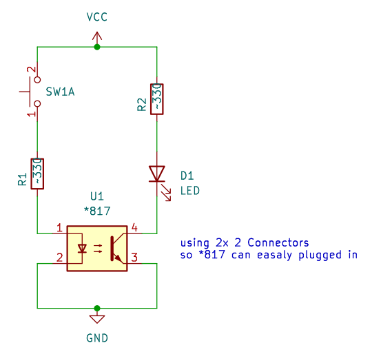
- Quick Test – Push the switch, and if the LED lights, the optocoupler basically works.
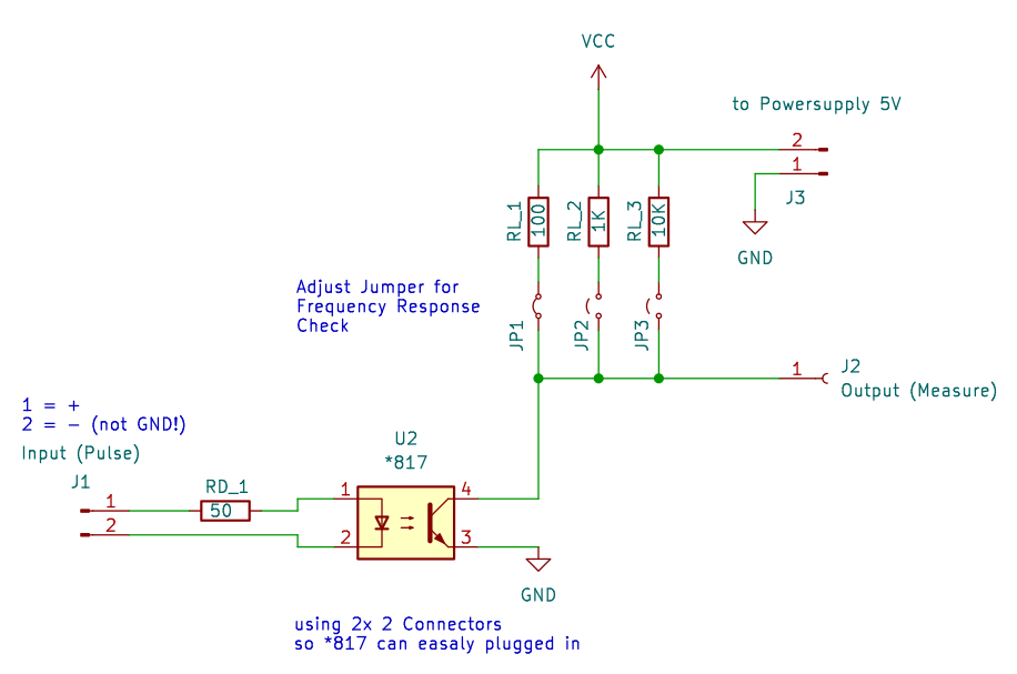
- Frequency Test – Based on the circuit from the datasheet. Input impedance is 50 Ω, and the output can be pulled up with 100 Ω, 1 kΩ, or 10 kΩ to see how the device behaves at different frequencies.
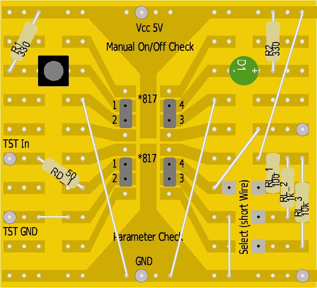
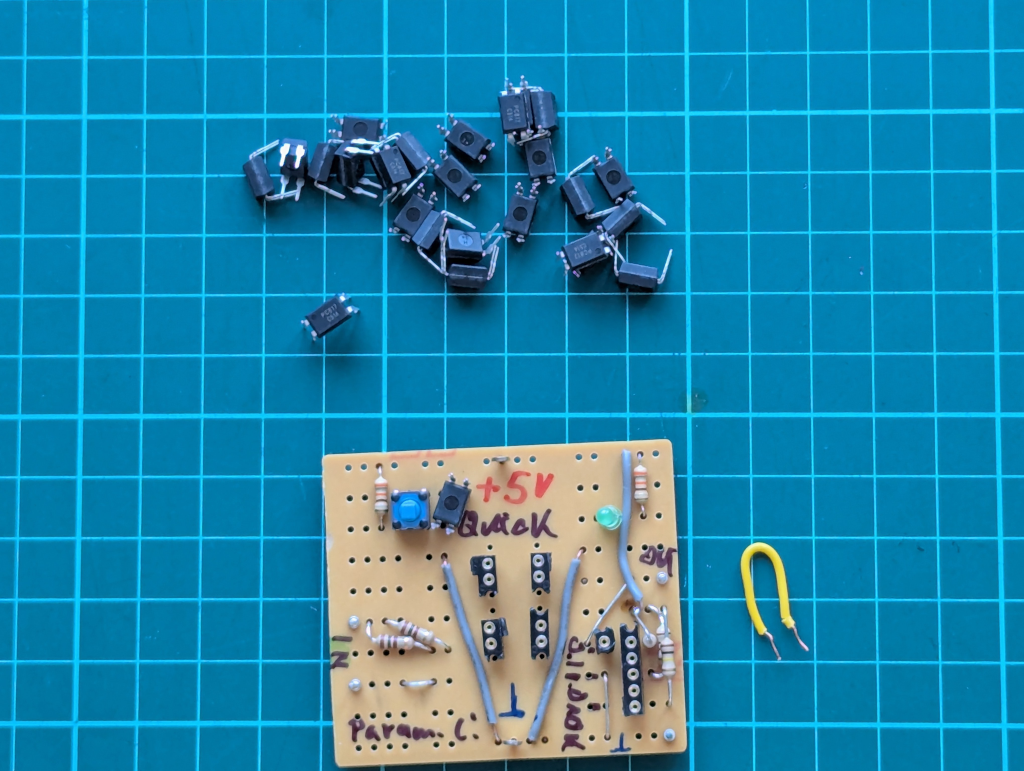
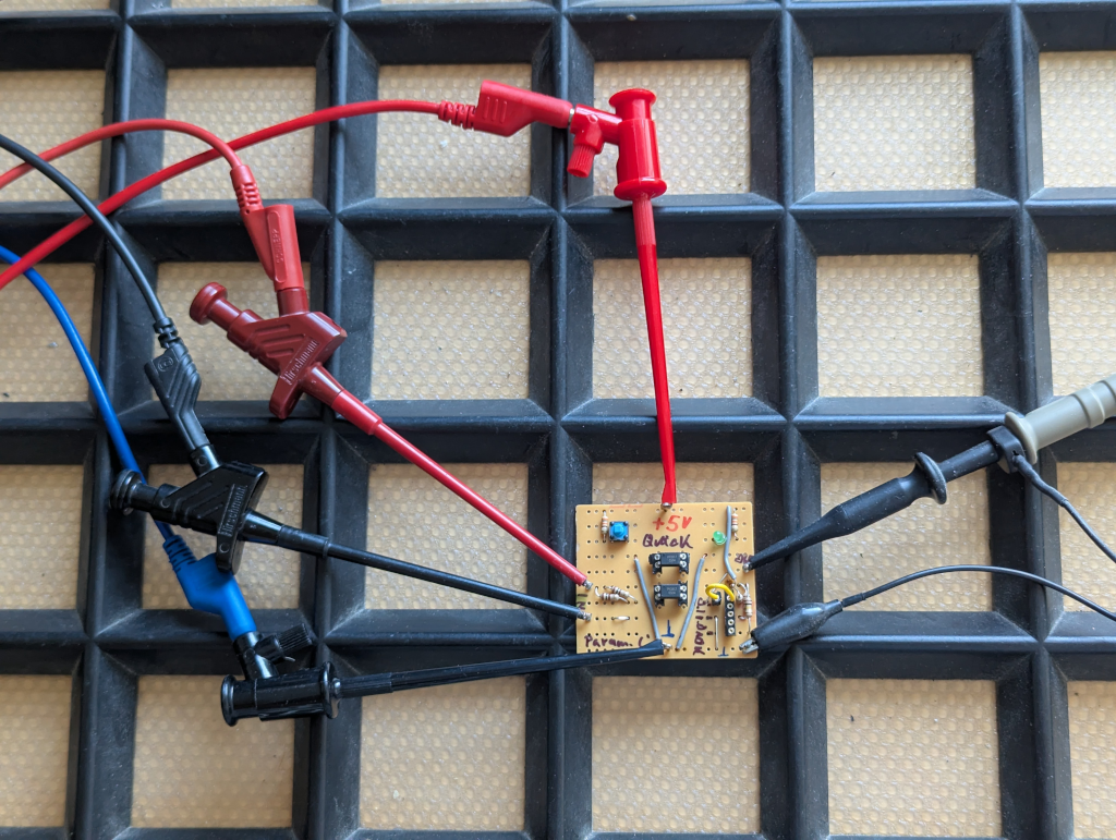
Simple stripboard:
That’s it.
It’s not meant to be fancy—just a tiny 2-hour project to get reliable data and a feel for how different PC817 batches respond.
The project data will be on Gitea – ToGo-Lab, Project ID 0002,
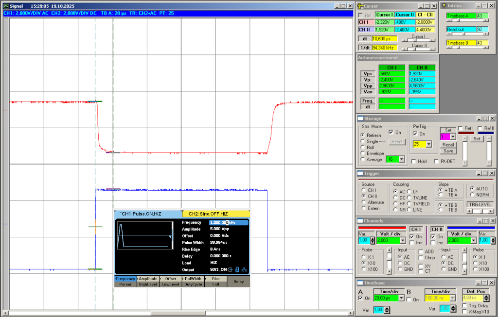
As working proof, some simple scope screenshots:
If you’re into optocouplers or small test circuits, feel free to build along or suggest tweaks.
Always happy to hear what others find useful in their own setups. 🙂