電車ベクトル (Train Vector): The Software

Short overview

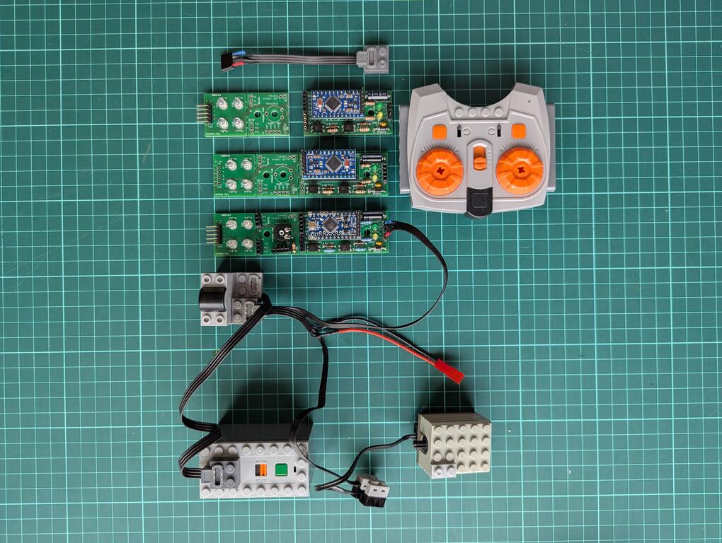
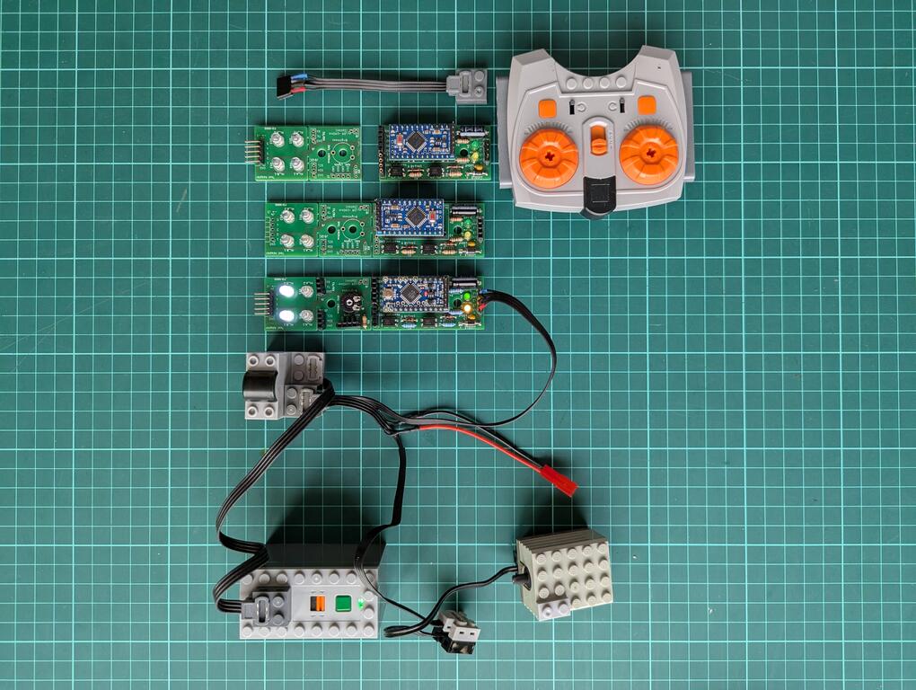
This is the software description of the 電車ベクトル (Train Vector) project (link to overview). The hardware side (link to description) isolates and prepares the motor signal, but the real decision how to light the LEDs is done in software.

Because the signal comes from a noisy H-bridge motor controller, the software has to do more than just one raw read and one if statement.

The actual Arduino sketch is here in the git subfolder: https://gitea.togo-lab.io/tgohle/0004-DenshaBekutoru/src/branch/master/firmware/ArduinoTest/DenshaBekutoru-0004_Version-0-2_ProMini_PCB2026-2_V01

In Summary

The software is the part that turns the noisy input from the hardware into a stable direction decision. It does that by:

  • averaging the analogue inputs,
  • calibrating itself at startup,
  • building a threshold from the real idle behaviour,
  • using hysteresis,
  • remembering the last valid direction,
  • driving the outputs accordingly,

Basic idea

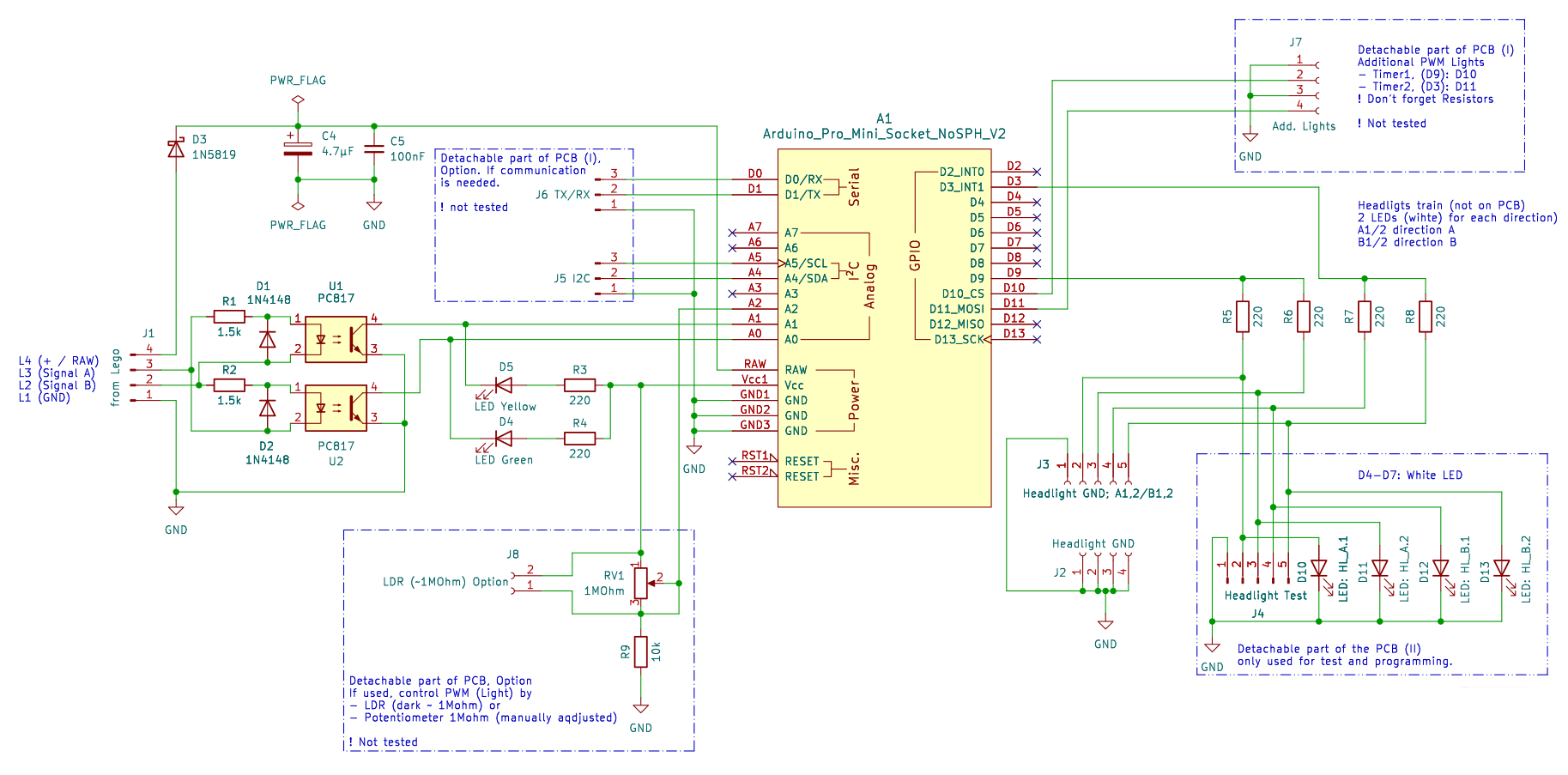
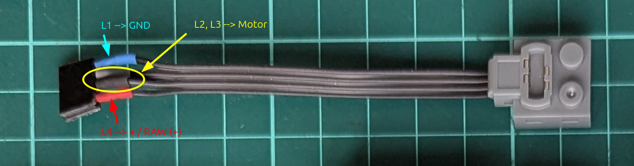
The software reads two analogue voltages from the optocoupler output stage:

  • ADC_PIN_1 = A0
  • ADC_PIN_2 = A1

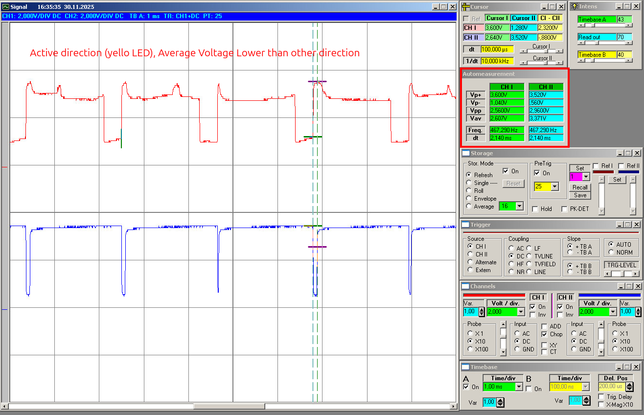
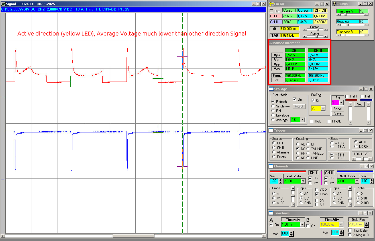
These two signals represent the processed motor direction information. If the motor is driven one way, one side will dominate. If the motor is driven the other way, than the other side will dominate. So the basic software idea is to compare both voltages and evaluate the difference:

  • diff = v1 - v2

If diff is clearly positive, the software decides for direction 1.
If diff is clearly negative, the software decides for direction 2.
If the difference is too small, the software does not change direction and simply keeps the last valid state.

That last point is the important one. It means the headlights do not start flickering just because the motor is stopped, the signal is weak, or the input is sitting in some noisy neutral area.

First step: averaging the analogue inputs

The first thing, after power on: The sketch averages the inputs over a time window. This is done in:

  • measureAveragedVoltages()

The code samples both analogue channels repeatedly over:

  • SAMPLE_WINDOW_MS = 100
  • SAMPLE_DELAY_US = 500

So instead of reacting to one random noisy measurement, the software builds an average value for both channels:

  • v1
  • v2

This is one of the most important parts of the program, because the motor signal is not clean. Without averaging, the later direction decision would be much more unstable.

Second step: calibration when nothing happens

At startup, the software assumes there is no real movement yet. That is the moment it uses to adapt itself to the actual build, controller, and wiring. This is done in:

  • calibrateVdiffThreshold()

The sketch performs multiple averaged measurements at boot:

  • AverageRepeat = 100

For each of these measurements it calculates:

  • |v1 - v2|

This gives the natural mismatch between both channels when no real direction decision should happen yet. Because even in the idle case both channels are usually not perfectly identical, the software does not assume zero. Instead, it measures the real baseline. The measured values are sorted, and then the median is taken:

  • VdiffBaseline = median(|V1-V2|)

I think this is a good choice, because the median is less sensitive to single bad spikes than a simple average. From this baseline, the code builds the real decision threshold:

  • VdiffThreshold = max(VdiffBaseline * 1.5, 0.03V)

So the threshold is:

  • adapted to the real hardware setup
  • increased by a margin
  • never allowed to go below a minimum floor

This is exactly the part that should help the board work with different train builds and different controllers without having to hard-code one fixed voltage value.

Third step: threshold and hysteresis

Once the baseline threshold is known, the software creates two limits:

  • T_hold
  • T_enter

These are derived from the calibrated threshold:

  • T_hold = 1.0 * VdiffThreshold
  • T_enter = 2.0 * VdiffThreshold

This creates a small hysteresis system. The idea is:

  • if the signal difference is very small, hold the old direction
  • if the signal difference is clearly strong, allow a direction change
  • in between, still hold the old direction

So the software does not switch direction the moment the signal only barely crosses one border. That makes the behaviour much more stable.

The state machine

The actual state machine is very simple and handled in:

  • updateDirectionFromVoltages()

mainly State machine (direction memory) + Hysteresis (Version A)

I use two thresholds:

  • T_hold (smaller): below -> treat as neutral and HOLD state
  • T_enter (larger) : above -> allow direction change (set by sign)

Behavior:

  • If |diff| = T_enter : set direction by sign
  • Else (between) : hold direction

Presets (implemented as multipliers of the calibrated VdiffThreshold):

  • T_hold = 1.0 * VdiffThreshold
  • T_enter = 2.0 * VdiffThreshold
  • Inputs derived from v1, v2: diff = v1 – v2

This means the software remembers the last valid direction and does not jump around in the weak or noisy range.

Output logic

Once the state machine has decided the direction, the outputs are updated in:

  • applyDirectionOutputs()

The output pins are:

  • LED_DIR1_PIN = 3
  • LED_DIR2_PIN = 9

The code first switches both outputs off and then activates only the matching one:

  • direction 2 -> D3 on
  • direction 3 -> D9 on

So at the moment the output stage is simple:

  • one direction = one output active
  • the other direction = the other output active

This is enough for the basic headlight function.

The sketch also includes a small startup blink sequence in:

  • initBlinkSequence()
  • blinkLED()

That is mainly useful to see directly that the board is alive after power-up.

Main loop behaviour

After setup and calibration, the loop is very simple:

  1. measure both averaged input voltages
  2. update the direction state
  3. apply the outputs
  4. print debug values to serial
  5. wait a short time

The delay at the end is:

  • delay(300)

So this is not written as a super-fast control loop. It is written as a stable and easy-to-observe detection loop, which makes sense for this kind of project stage.

Serial output for debugging

For debugging, the code can print all important values to serial output.

This is controlled by:

  • SerialOutputAllow

The function is:

  • serialPrintAll()

The output includes:

  • v1
  • v2
  • |v1-v2|
  • VdiffBaseline
  • VdiffThreshold
  • T_hold
  • T_enter
  • current direction

For development this is useful, because it makes it much easier to see why the software made a certain decision and how well the calibration worked.

Overview of the used functions

Here is a short overview of the most important functions in the sketch:

  • blinkLED()
    Small helper to blink one output LED

  • initBlinkSequence()
    Startup blink pattern to show the board is alive

  • applyDirectionOutputs()
    Switches the output pins according to the current direction state

  • measureAveragedVoltages()
    Reads both analogue inputs over a time window and calculates averaged voltages

  • sortFloatArray()
    Sort helper used during calibration

  • medianOfSortedFloatArray()
    Returns the median value from the sorted calibration data

  • calibrateVdiffThreshold()
    Measures the idle mismatch at startup and creates the calibrated threshold values

  • updateDirectionFromVoltages()
    The actual direction decision logic with hysteresis and direction memory

  • serialPrintAll()
    Prints all relevant measured and calculated values for debugging

  • setup()
    Initialises serial, pins, calibration, startup blink, first direction update

  • loop()
    Repeats measurement, state update, output update, and debugging output

電車ベクトル (Train Vector): The Hardware

Short overview

This is the HW description of the 電車ベクトル (Train Vector) project I described in this overview.

The main job of the hardware is to retrieve and process the signal direct from the motor, so that it can be used by the Arduino’s analogue input. The Arduino then does the magic and controls 4 LEDs (2 for each direction). The hardware will also have some additional features, so I can send out 2 more signals as a future option and also expose the I2C and TX/RX lines of the Arduino. There will also be a future option to control the brightness of the LEDs via PWM, controlled by a variable resistor or light (LDR). All this has to fit on a very small PCB, using the typical brick size.

The schematic is built around these main blocks:

  • input signal processing
  • Arduino Pro Mini 5V as controller, also providing the 5V needed
  • output section for the headlights
  • test circuit
  • future options
0004-DenshaBekutoru_v0.2_schematics

The PCB is split into 3 sections

  • signal processing and controller board / section
  • future options (light PWM and communication) section
  • test circuit section

All details, including KiCad files, you will find in the ToGo-Lab Gitea.

Input signal processing

To get the signal from the brick-type motor or controller, I adapted this brick wire. In the picture you will see where the supply voltage, ground, and the motor wires are located. This connects to J1 in the schematic.

0004-DenshaBekutoru_v0.2_Connector

The input side reads the motor-related signals and prepares them for the controller. Because this is taken directly from the motor via J1, the signal is neither clean logic nor directly usable by the Arduino analogue inputs. It comes with switching noise, polarity changes, and inductive effects. Also, the voltage is too high to be properly handled later by the analogue inputs.

In the schematic, the parts doing this are: R1, R2, D1, D2 (input protection for the LEDs in the optocouplers) and U1, U2 = PC817 optocouplers.

To keep the controller side safer and cleaner, I used two isolated input channels with PC817 optocouplers (that was also the reason why I built a small tester for optocouplers). These optocouplers will act as rectifiers due to the polarity change (J1-3 and J1-4).

R3 and R4 together with D4 and D5 are used for pull-up, signalling (also for debugging), and of course to deliver voltage to the phototransistor in the optocoupler.

The signals will at the analoge inputs will show like this (slow, mid power, as example):

Arduino Pro Mini 5V as controller

For the controller I used an Arduino Pro Mini 5V / 16 MHz. It is small enough, I have reset logic on it, and also a power supply, so I can use the voltage directly from the remote controller. The on-board power supply will also be used to feed the optocouplers.

The Pro Mini is small, cheap, easy to replace and I understand how to program it because my programming skills are limited, I am more the HW guy, but feel free to use your own prefered µC. It is also more than powerful enough for this job and has everything needed to do analogue measurement and drive some LEDs. Another advantage is that the Pro Mini keeps the design easy to reproduce later for a DIY kit. No special programmer or unusual module is needed.

Output, future options, and test section

On the output side I used Arduino pins D3 and D9 for the two direction outputs. I used D3 and D9 because both pins support hardware PWM. The current version mainly uses them as normal outputs, but this keeps the option open for later LED dimming and other light-control functions without changing the hardware.

At the moment it is not tested; the basic function is only on/off switching of the headlights according to direction. But I wanted to keep the option open to dim the LEDs later. That could be useful for a more realistic light level, different train setups, or later expansion ideas.

Each direction drives two white LEDs in parallel, with each LED (D10, D11, D12, D13) having its own series resistor (R5, R6, R7, R8).

The future options are PWM control by resistor (RV1 and R9). You can replace RV1 with an LDR. There are also connectors for communication: I2C and TX/RX and 2 extra digital outputs to drive LEDs.

The LEDs later will be the ones in the train, so I placed the LEDs you see in the schematic on the test part of the PCB. To connect them from the mainboard I added the connectors J2 and J3.

Main PCB

The main PCB contains the complete working circuit:

  • motor-side input connection
  • isolated signal processing
  • Arduino Pro Mini socket
  • main headlight outputs
  • basic support parts

This is the board that matters. If somebody only wants the core function, this is the section that needs to work. You can detach the future options part and also the test part.

The layout was done with a small footprint in mind, because the board is intended to sit inside a brick-built locomotive, where space is always limited.

0004-DenshaBekutoru_v0.2_PCB

Additional detachable section

There is also an additional detachable PCB section. This part is not required for the core function, but it gives room for expansion without changing the main board concept too much. In the current design this includes optional extra light outputs and an option for brightness control, for example via LDR or potentiometer. This part also expose the pins for communication, I2C and TX/RX.

Test section

I also included a small test section on the PCB. This is simply practical. For a board like this, bring-up is much easier if basic functions can be checked directly on the board before everything is installed in a locomotive. The test section helps to verify that the direction outputs behave as expected and that the board is alive before going into real use. Before installing it, you can cut this away easily.

電車ベクトル (Train Vector): Project Overview and Current Status

What this project does

電車ベクトル (“Densha Bekutoru” / Train Vector) is a small board for LEGO, BlueBrixx, or similar locomotives built from bricks. Its job is to detect the current driving direction and switch the front and rear lights (2 white LEDs for each direction) to match.

That is the whole point of the project: the train changes direction, and the lights should follow automatically. They also stay on if the train stops; only when the direction changes do the lights switch to the correct direction.

This is Project No. 0004 for my Togo-Lab hobby / side project and the first “full-blown” one, meaning the result should be a DIY kit ready for everybody to use.

You will find the project files (schematics, PCB, controller software) in my Git: https://gitea.togo-lab.io/tgohle/0004-DenshaBekutoru

Why detecting the direction from motor input is not as simple as it sounds

In theory, it should be easy: just look at the motor polarity, add a simple state machine in hardware or software, and done. But in reality it is not that simple.

The motor in such setups is driven by an H-bridge circuit to deliver different power levels = different resulting speeds. Therefore, the signal on the motor lines is not a nice, stable DC level. You get switching effects, noise, and inductive spikes from the motor. Depending on the controller, load, and wiring, the signal can look pretty messy.

As an example, the following pictures are oscilloscope readings for one direction, let’s say direction “A”.

minimum power (slow speed):

20251026_Direction_A-Slow

maximum power (high speed):

20251026_Direction-A-Fast

You will notice the noise and, making the problem even worse, the inductive voltage, so you get reverse voltage as well. Simply installing an LED and resistor would result in flickering in each direction, with the level depending on speed. But this is of course not the right thing for a headlight.

So the challenge is not just detecting a direction once and using a state machine. The challenge is to sense the direction only from motor voltage and get rid of flickering, inductive voltages, and reactions to every little disturbance.

The current approach I use

My idea was to use two isolated input channels via optocouplers and a small controller (Arduino Pro Mini 5V type) to evaluate the motor-side signals. This should be small enough to fit the other constraint as well: the small footprint / volume, because this will be installed in the train, meaning there is very little space, and it needs to match the size of typical bricks.

On the software side, I did not go for a super simple “read once and switch” solution. The firmware works with averaging, calibration, and hysteresis so that short spikes or unstable transitions do not immediately flip the detected direction.

I hope this will make it also usable for a wide range of controllers, from low-cost Chinese controllers up to the official ones.

Current status

At this point in March 2026, I have a working design = hardware PCB and a working version of the software. The current version 2 (beta) hardware is built and working. Three PCBs were produced, assembled, and tested. The Arduino code was written to fit the actual HW setup, but so far it shows only the very basic function: switching lights according to direction.

I think the project is in a good beta state: real hardware exists, it works, and it is ready for practical testing. My colleague, who originally asked for this circuit for his hobby use, will show and use it in his model train club. I hope for real-life testing. This will give much better input than bench testing alone.

PXL_20260308_111601647_copy

So the current version 2 works, but it is still beta.

Related posts

In the next blog posts I will describe:

Outlook

Maybe there will be a version 3, depending on the input. I also hope that some of the club members will want this hardware as well, so I will design version 3, and this would also be the first DIY kit and the transition from beta to the first “official” version.

Post-Mortem: Antivirus Integration on a 1 GB Nextcloud VPS (failed due load)

Failing Experiments Are Useful

Today I tried to push my togo-lab.io setup (see 2nd block at my landing page for all services) a bit further than strictly necessary. So maybe you noticed some outages.

Why I did this? Not only for production security reasons, but also out of curiosity: How far can I go with limited resources? I want to understand where the real limits for my setup are.

In this experiment, I wanted to see whether a single small VPS could reasonably host Nextcloud, a Matrix server, and Gitea, and still handle antivirus scanning for file uploads. At first glance it looked tight, but maybe possible. In practice, it pushed this small VPS over the edge.

That outcome was useful for my learning and understanding. When things fail or become unstable, I usually learn much more than when everything works smoothly. As a technician, breaking things on purpose for learning is, for me, typically the fastest way to understand them.

The following section is a post-mortem of that experiment: what it revealed, what I learned from it, and what would be required if I want to add antivirus scanning in the future.


Context:
This server hosts multiple self-managed services on a small VPS (1 GB RAM, 1 vCPU):

  • Nextcloud (primary collaboration platform)
  • Matrix server
  • Gitea
  • Supporting stack (PHP-FPM, MariaDB, Redis, Apache/Nginx, Fail2Ban)

The goal was to add antivirus scanning for uploaded files in Nextcloud, as preparation for future collaborative use.


Initial Goal

Enable server-side antivirus scanning for Nextcloud uploads using ClamAV, with the following constraints:

  • Lightweight
  • Automated
  • No interactive maintenance
  • Suitable for a self-hosted environment

This is a reasonable baseline requirement once multiple external contributors are involved.


Attempted Approaches

1. ClamAV Daemon (clamd) + Nextcloud (Socket Mode)

What was tried

  • Installed ClamAV daemon

  • Tuned clamd.conf aggressively (single thread, reduced parsers, size limits)

  • Added strict systemd memory limits

  • Disabled background scans

  • Socket-based integration with Nextcloud

  • **changes to the default /etc/clamav/clamd.conf

          # === VPS-safe limits ===
          MaxThreads 1
          ConcurrentDatabaseReload no
    
          # File size limits (Nextcloud uploads)
          MaxFileSize 50M
          MaxScanSize 75M
          StreamMaxLength 75M
    
          # Archive / recursion limits
          MaxRecursion 10
          MaxFiles 5000
    
          # Timeouts
          ReadTimeout 120
          CommandReadTimeout 120
    
          # Disable low-value / memory-heavy scanners
          ScanHTML false
          ScanMail false
          ScanSWF false
          ScanHWP3 false
          ScanXMLDOCS false
    
          # Reduce bytecode impact
          Bytecode true
          BytecodeTimeout 20000
    
          # Reduce RAM further (Nextcloud upload use-case)
          PhishingSignatures false
          PhishingScanURLs false
          DisableCache true
          ExtendedDetectionInfo false
  • best I got, via free -h

total used free shared buff/cache available
Mem: 960Mi 926Mi 68Mi 31Mi 101Mi 33Mi
Swap: 1.0Gi 843Mi 180Mi
    $ swapon --show
    NAME      TYPE  SIZE   USED PRIO
    /swapfile file 1024M 848.5M   -2`

Observed behavior

  • clamd resident memory usage: ~500–600 MB
  • Heavy swap usage even after tuning
  • Periodic stalls, SSH lag, partial service unresponsiveness
  • OOM kills during database reload or startup

Conclusion Even heavily tuned, resident ClamAV is not viable on a 1 GB VPS that already runs multiple services.


2. ClamAV Executable Mode (clamscan on upload)

What was tried

  • Disabled clamd entirely
  • Used Nextcloud Antivirus for Files app in Executable mode
  • Scanning only on upload
  • Strict size limits
  • No background scans

FYI Final authoritative configuration in NextCloud App “Antivirus for Files”

  • Mode: ClamAV Executable
  • Path to clamscan: /usr/bin/clamscan
  • Extra command line options (comma-separated): --no-summary,--infected,--max-filesize=50M,--max-scansize=75M
  • Stream Length: 104857600
  • Block uploads when scanner is not reachable: Yes
  • Block unscannable files: No
  • Background scans: effectively off (unchecked)

Observed behavior

  • Technically functional
  • No permanent memory footprint
  • However:
    • Uploads caused noticeable CPU + IO spikes
    • PHP-FPM workers stalled under load
    • Combined service activity still led to instability

Conclusion Even non-resident scanning adds too much peak load for this VPS when combined with:

  • Nextcloud
  • Matrix
  • Gitea
  • Database and cache services

Final Decision

Antivirus disabled (for now)

The Nextcloud Antivirus app is currently disabled.

Reasons:

  • System stability has higher priority than partial security measures
  • Trusted users only
  • Strict file permissions
  • Regular backups
  • No public upload endpoints

After disabling AV and rebooting:

  • System became stable
  • Swap usage normalized
  • All services responsive:
    • Nextcloud
    • Matrix
    • Gitea

Post-Mortem Summary

Item Result
Configuration error ❌ No
ClamAV bug ❌ No
Nextcloud bug ❌ No
VPS resource limit ✅ Yes
Wrong architecture ✅ Yes (for this size)

Meaning:

  • This was not a misconfiguration.
  • It was a capacity mismatch.

Lessons Learned

  1. 1 GB VPS is already at the limit for:

    • Nextcloud
    • Matrix
    • Gitea
      combined.
  2. Antivirus scanning is loadwise not “free”, even in executable mode.

  3. Security features that trigger CPU + IO spikes must be sized for worst-case concurrency, not idle averages.

  4. Adding AV without increasing resources creates negative security by destabilizing the system.


When Antivirus Will Be Re-Enabled

Antivirus scanning will be mandatory once this instance is used for real group collaboration.

That will require one of the following options:

Option A — VPS Upgrade (actual preferred)
  • Upgrade to ≥ 2 GB RAM
  • Re-enable ClamAV (daemon or executable mode)
  • Keep all services on one host
Option B — Service Split
  • VPS 1: Nextcloud
  • VPS 2: Matrix + Gitea
  • Antivirus enabled only on Nextcloud host

Current Security Posture (Interim)

  • If, than only trusted users
  • No public upload endpoints
  • Strict permissions
  • Fail2Ban + firewall
  • Frequent backups
  • Fast restore tested

This is acceptable temporarily, but not a final state.


Closing Notes

This experiment was intentional and valuable, learned a lot, also during configuration and tuning.

It clarified:

  • the real resource cost of antivirus scanning
  • the practical limits of small VPS setups
  • and the architectural decisions required for future growth

When collaboration expands, the infrastructure will be expanded accordingly. So clamav and configuration stays, but Nextcloud App is disabled for now, but not uninstalled.

TōGō-Lab now on Matrix

I’m happy to share that the TōGō-Lab Matrix server is now up and running and officially open for productive use. This is a self-hosted Matrix instance, dedicated to discussions around my hardware projects. It hope, it will gives you and me an open and privacy-respecting way to chat, collaborate, and exchange ideas.


Public Lobby

The main entry point is the public lobby, where everyone can join and get oriented: From there, invitations to project-specific rooms are handled. All project rooms are end-to-end encrypted (the lobby itself is intentionally open).

Why I made this

Idea is to bundle Discussions around ToGo-Lab hardware projects, design ideas, experiments, and implementation details. This space complements Git repositories and the blog as an additional communication channel. If you’re interested in a specific project (as referenced here on the blog or on Git), feel free to drop by the lobby and start a conversation with me.

Alternative / public Matrix presence

In addition to this self-hosted, project-dedicated server, there is also a public space on matrix.org. This is mainly for broader, non-project-specific exchanges. Same idea, feel free and show up in the TGONet-Lobby.


If you’re already using [Matrix](https://en.wikipedia.org/wiki/Matrix_(protocol) (Element, Fractal, or some another client), just jump in, so we can talk.

Hope to see you there soon.

togo-lab MATRIX Lobby_round

PC817 Optocoupler Tester – Lazy Sunday Afternoon Project

For some upcoming projects, I’ll use the PC817 optocoupler family. But sadly, you don’t always get what you think you’ve bought. So how can you simply check if they work as described in the datasheet? I wanted a quick way to verify parts before building them in.

This small tester consists of two independent circuits, runs on 5 V, and does two simple things:

  1. Quick Test – Push the switch, and if the LED lights, the optocoupler basically works.
OptoCoupler_CheckCircuit_QuickManual
  1. Frequency Test – Based on the circuit from the datasheet. Input impedance is 50 Ω, and the output can be pulled up with 100 Ω, 1 kΩ, or 10 kΩ to see how the device behaves at different frequencies.
OptoCoupler_CheckCircuit_ParameterCheck

Simple stripboard:

0002-PC817-Series-PhotoCoupler-Tester_SB

That’s it.
It’s not meant to be fancy—just a tiny 2-hour project to get reliable data and a feel for how different PC817 batches respond.
The project data will be on Gitea – ToGo-Lab, Project ID 0002,

As working proof, some simple scope screenshots:

If you’re into optocouplers or small test circuits, feel free to build along or suggest tweaks.
Always happy to hear what others find useful in their own setups. 🙂

Controlling my Siglent SDG2042X from Linux

As part of rebuilding my electronics test bench for future projects at ToGo-Lab, I wanted a simple way to control my Siglent SDG2042X remotely from my Ubuntu box. So I wrote a small PyQt5 GUI script.

In its current state, the script lets you:

  • Select waveform, amplitude, frequency, and DC offset
  • Run sweeps, bursts, or arbitrary waveforms
  • Save and recall up to 10 presets (you can also recall directly from the generator)
  • Use the ARB Manager to download waveforms from the generator or upload new ones (not fully tested yet!) – it also shows the waveforms currently stored
  • Send direct SCPI commands through a built-in CLI
  • Grab screenshots from the generator display (saved in the same directory as the script)

Use it as-is or tweak it for your own setup. Programming in Python and PyQt5 isn’t my main profession -(I’m more of a hardware guy) so if you try it and find bugs (there will be some), I’d love to hear from you.

Script source and details: ToGo-Lab Git Repository

The program talks to the SDG2042X over a simple socket connection on port 5025 using SCPI commands. You can call the script with the -ip parameter (try also --help). This is handy if you launch it via a .desktop file.

The functions are straightforward, so there’s no detailed documentation yet. I hope most of the features are self-explanatory. Each GUI tab covers one main function. See more details in the Gitea repo:

  • Basic: Waveform, frequency, amplitude, offset, phase, and output control
  • Burst: Configure burst mode, trigger source, cycles, and delay
  • Sweep: Set up linear or logarithmic sweeps, start/stop frequency
  • ARB Manager: List, upload, and download arbitrary waveforms (still experimental)
  • SCPI CLI: The command-line interface for direct SCPI communication
  • Presets: Store and recall up to 10 custom setups; presets are saved in a text-based .dat file. This tab is especially useful: You can adjust settings directly on the generator, then read them back and save them as presets. The file is easy to edit manually if needed.

You can take screenshots at any time. They’re stored as .bmp files in the working directory, with the date and time included in the filename.


Update 2025-10-25

My SDG2042X Python control GUI keeps moving forward. Today I spent a lot of time reviewing and rewriting parts of the code. My focus was on stability & usability, and making the tool to fit better into my idea of a remote controlled test bench setup.

Today’s update:

Context-aware Basic Tab The parameter fields now change automatically depending on the selected waveform. So if you choose SINE, SQUARE, RAMP, PULSE, NOISE, ARB, or DC, you’ll only see the options that actually matter, others are grayed out.

Improved SCPI Reliability I added a new query_retry() function and a socket drain, which makes communication with the generator more reliable. This prevents annoying timeouts when running queries like OUTP? or BSWV?. The default socket timeout has also been set now to 4 seconds to give things a bit more breathing room (especially the screenshots are very slow). This makes it a little bit laggy but with shorter time I get sometimes errors. Adjust with care if you want a shorter response time.

Config System There’s now an SDG2042x.config file where you can define paths for presets and screenshots (simple text file). The pathes for presets and schreenshot directory are accessable from the “Config” tab.


Screenshot from 2025-10-25 15-45-33
Screenshot SDG2042X

Old meter (MXD-4660A), new tricks.

I pulled my veteran DMM, a Voltcraft MXD-4660A, from the drawer to set up my workbench (adding a serial-to-USB converter) and gave it a second tour of duty with QtDMM on Ubuntu. After a bit of searching online what to use under I found the QtDMM project at http://www.mtoussaint.de/qtdmm.htmlm , but appears abandoned. The active fork, I think, is at https://github.com/tuxmaster/QtDMM.

Here’s the final install and setup for my lab computer running Ubuntu 22.04 (Jammy):


Build & Install QtDMM on Ubuntu 22.04 (Jammy)


1) Prerequisites

  • Enable Universe and base tools:

    sudo apt update
    sudo apt install -y software-properties-common
    sudo add-apt-repository -y universe
    sudo apt update
  • Compilers, build tools, VCS:

    sudo apt install -y git build-essential cmake ninja-build pkg-config
  • Qt6 SDK

    sudo apt install -y qt6-base-dev qt6-tools-dev qt6-tools-dev-tools qt6-l10n-tools libqt6serialport6-dev
  • HID API

    sudo apt install -y libhidapi-dev libhidapi-hidraw0
  • OpenGL headers for Qt6Gui/Widgets

    sudo apt install -y libopengl-dev libgl1-mesa-dev libglu1-mesa-dev mesa-common-dev
  • Serial access without sudo:

    sudo usermod -aG dialout "$USER"
  • Log out and back in to apply group membership

2) Get the source and make the script executable

git clone https://github.com/tuxmaster/QtDMM.git
cd QtDMM
chmod +x compile.sh

3) Build

  • Clean build (optional). Also verifies prerequisites are present.
    ./compile.sh clean || true
    rm -rf build CMakeCache.txt CMakeFiles
    ./compile.sh
  • Artifacts land in ./bin/:
    ./bin/qtdmm --version
  • Verify it runs. If not, see Troubleshooting below

4) Install for all users (see §5 for a .deboption)

Preferred:

sudo ./compile.sh install
# now on PATH:
qtdmm --version

5) Alternative: make a .deb

Keeps your system clean and is easy to remove later.

./compile.sh pack
sudo apt install ./QtDMM_*amd64.deb

6) Uninstall

If installed via .deb:

sudo apt remove qtdmm

If installed via compile.sh install:

# run from the same build dir used for the install
sudo xargs rm < build/install_manifest.txt

Troubleshooting:

If you hit errors, try a clean build reset instead of first searching forums. I learned the hard way to make a clean install as a belt-and-suspenders reset, that deletes built objects but keeps the CMake cache.

  • “|| true” lets the sequence continue even if the clean step fails due to a broken config.
  • “rm -rf build CMakeCache.txt CMakeFiles” force-removes any stale out-of-source build dir and any accidental in-source CMake cache:
  • “Final ./compile.sh” does a fresh configure and build:
cd ~/QtDMM
./compile.sh clean || true
rm -rf build CMakeCache.txt CMakeFiles
./compile.sh

Let’s check if it’s running

  • As your regular user, start QtDMM from the command line or via the Ubuntu Dock (search for “QtDMM”):
  • Hint: How to create a Desktop shortcut launcher for ubuntu 22.04
    QtDMM - Running

  • Configure settings for MXD-4660A:
    Setup Voltcraft MXD-4660A

    Final test setup (send a known signal) and the result: MXD getting some imput from generator to prove reading
    QtDMM running, getting Data


Question to readers: Is there Linux software for the old Hameg HM1507-3? I’m currently using a Windows XP VM with very old software.

“Hello World” Project for Tōgō Lab: FireFly Morse Blinker

This is my first hardware project on the new ToGo-Lab.io server.

Some years ago, when I started with AVR/ATTiny programming, I built a tiny Morse “throwie”: one ATtiny, one LED, one resistor, and power-friendly firmware. The goal was to use as few parts as possible to keep it cheap, while still adding a couple of useful functions.

Two main functions: Detect daylight. If it’s bright, sleep; if it’s dark, send a Morse message. The LED doubles as a light sensor.

This is a good restart for my new project home, https://togo-lab.io/, the HW version of a “Hello World” program. So I don’t plan heavy hardware work here, though I may add a small solar cell to stretch battery life. This version adds a supercapacitor and small solar cells and uses the LED as a light detector, so it only blinks in the dark. It’s no longer a throwie, more of a pendant. Hang it where it gets daylight and stays dry. It charges by day and blinks by night.

Yes – I want also a PCB and maybe you will the final result as a little DIY Project on e.g. – Tindie.

But real goal is to define the specs and a simple, repeatable workflow from Idea to real DIY Kit especially for bigger future projects.

This post will evolve as the project advances. I’ll append notes, design decisions, and lessons learned rather than writing a single post-mortem at the end. But don’t expect too much progress too quickly; this is a side hustle. Perhaps in a few years, after I retire, it will become one of my main activities.


What it is

  • DIY-Kit goal: beginner-friendly soldering kit with clear docs and hackable programm (using Arduino IDE).
  • MCU: ATtiny45/85, through-hole.
  • Power: 3–5 V, with solar + supercap option.
  • Behavior: Morse message presets, LED as light sensor for night-only blink.

Process and tooling

Roadmap

  • v0.1: Proto: breadboard + first PCB, single message, speed presets.
  • v1.0: Pilot: build guide, BOM with alternates, pilot of 10 units.
  • v1.1: docs polish, optional brightness setting, minor PCB tweaks.
  • v2.0: Zero Series

How this post will evolve
I’ll update this page with:

  • Schematics, Circuit description,
  • PCB Design, CAD. All you need to build one,
  • Build photos and assembly hints.,
  • BOM changes and sourcing notes,
  • Additional Blog post about the program itself and how to do with Arduino IDE.

Want to get involved?
Suggestions welcome. Open an issue on the repo or email tgohle@togo-lab.io. If you build one, share photos and your timing results—those will feed back into the docs and the next revision.


Schematics, Circuit description,
tbd

First Light at Tōgō Lab : Lab-Log Zero

I’m Thomas Gohle, and Tōgō Lab / 塔郷研究所 is my home base for future electronics projects.

About me: I studied RF communications in my youth, then spent the last few decades in semiconductor maintenance (details on LinkedIn).

I currently live in Dresden, Germany. With retirement on the horizon in some years, I’m rebooting my hobby. To my boss, if you’re reading this: it will take a while (you know how slow I can be). As you know I’m still working on current and upcoming equipment projects, and I still like to play with my wet-chemistry semicon beasts.

What can you expect? RF experiments, analog circuits, sensor builds and some digital electronics projects to some extend. I enjoy small AVR work, especially ATtiny. I document designs so they can be reproduced and improved by others. The midterm plan is to turn stable builds into small-batch kits and offer them to you. But making money is definitely not the goal of Tōgō Lab. The main goal is community, having fun, learning something new and doing things with my hands.

Collaboration lives on this server. Source code and issues are in Gitea at https://gitea.togo-lab.io. Shared docs and files that don’t fit into Gitea run through Nextcloud at https://nextcloud.togo-lab.io, which also supports basic project planning and control. This blog ties it together with build notes, measurements, and hard-won lessons. Some areas may be invite-only while the workspace settles.

Under the hood it’s a simple stack: Debian on a VPS and Apache with HTTPS via Let’s Encrypt, with a reverse proxy to services. I also keep a separate, older weblog you can find at my primary landing page https://tgonet.de. That older blog is shifting to private and travel notes (I like to travel, especially in the Far East), while Tōgō Lab here stays focused on electronics.

If RF, analog, and ATtiny projects are your thing, feel free to follow along, e.g., via my Mastodon account connected to Tōgō Lab. Ideas and pull requests welcome.