

What this project does
電車ベクトル (“Densha Bekutoru” / Train Vector) is a small board for LEGO, BlueBrixx, or similar locomotives built from bricks. Its job is to detect the current driving direction and switch the front and rear lights (2 white LEDs for each direction) to match.
That is the whole point of the project: the train changes direction, and the lights should follow automatically. They also stay on if the train stops; only when the direction changes do the lights switch to the correct direction.
This is Project No. 0004 for my Togo-Lab hobby / side project and the first “full-blown” one, meaning the result should be a DIY kit ready for everybody to use.
You will find the project files (schematics, PCB, controller software) in my Git: https://gitea.togo-lab.io/tgohle/0004-DenshaBekutoru
Why detecting the direction from motor input is not as simple as it sounds
In theory, it should be easy: just look at the motor polarity, add a simple state machine in hardware or software, and done. But in reality it is not that simple.
The motor in such setups is driven by an H-bridge circuit to deliver different power levels = different resulting speeds. Therefore, the signal on the motor lines is not a nice, stable DC level. You get switching effects, noise, and inductive spikes from the motor. Depending on the controller, load, and wiring, the signal can look pretty messy.
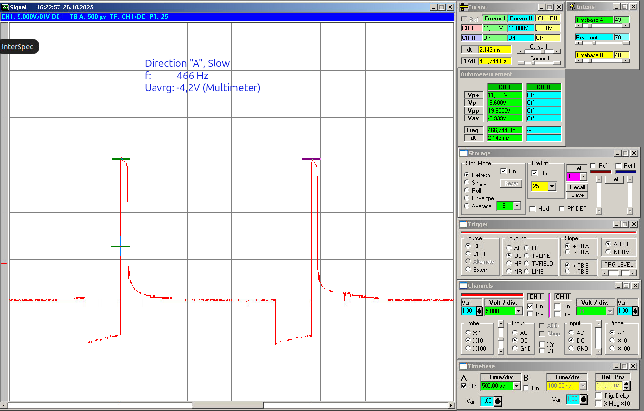
As an example, the following pictures are oscilloscope readings for one direction, let’s say direction “A”.
minimum power (slow speed):
maximum power (high speed):
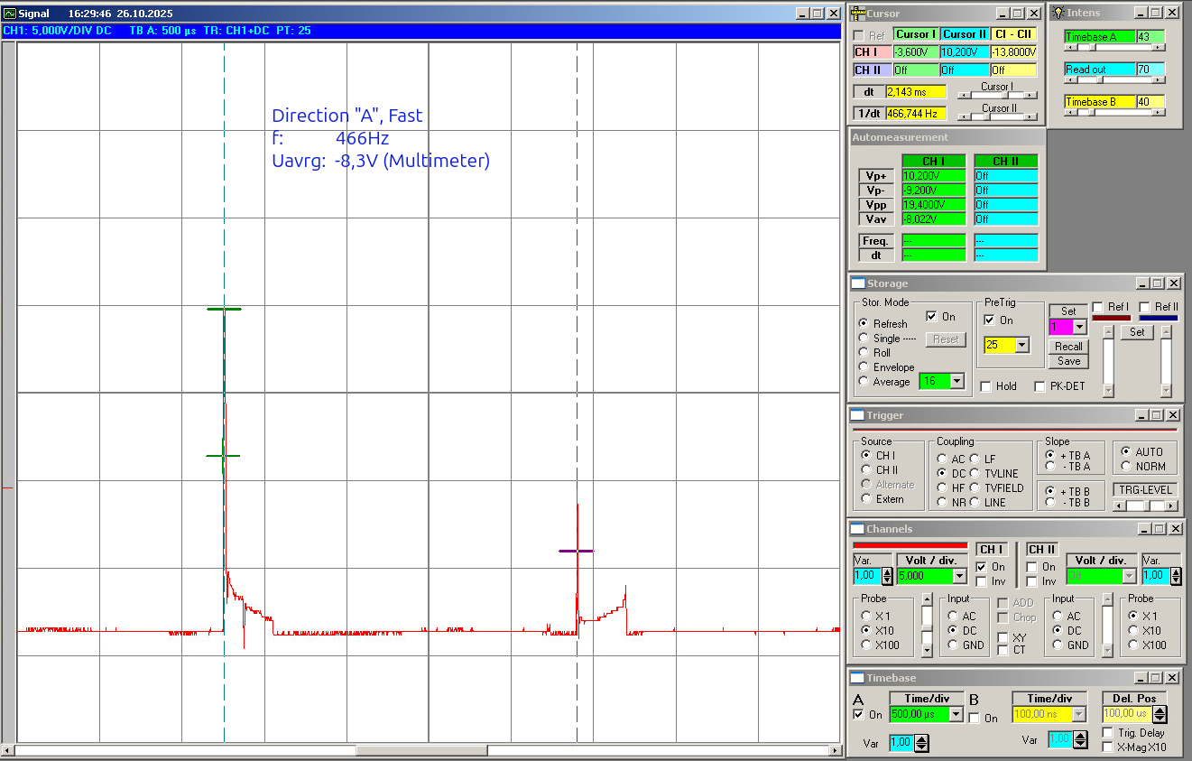
You will notice the noise and, making the problem even worse, the inductive voltage, so you get reverse voltage as well. Simply installing an LED and resistor would result in flickering in each direction, with the level depending on speed. But this is of course not the right thing for a headlight.
So the challenge is not just detecting a direction once and using a state machine. The challenge is to sense the direction only from motor voltage and get rid of flickering, inductive voltages, and reactions to every little disturbance.
The current approach I use
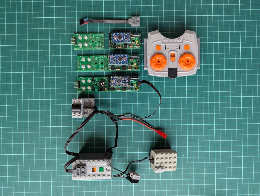
My idea was to use two isolated input channels via optocouplers and a small controller (Arduino Pro Mini 5V type) to evaluate the motor-side signals. This should be small enough to fit the other constraint as well: the small footprint / volume, because this will be installed in the train, meaning there is very little space, and it needs to match the size of typical bricks.
On the software side, I did not go for a super simple “read once and switch” solution. The firmware works with averaging, calibration, and hysteresis so that short spikes or unstable transitions do not immediately flip the detected direction.
I hope this will make it also usable for a wide range of controllers, from low-cost Chinese controllers up to the official ones.
Current status
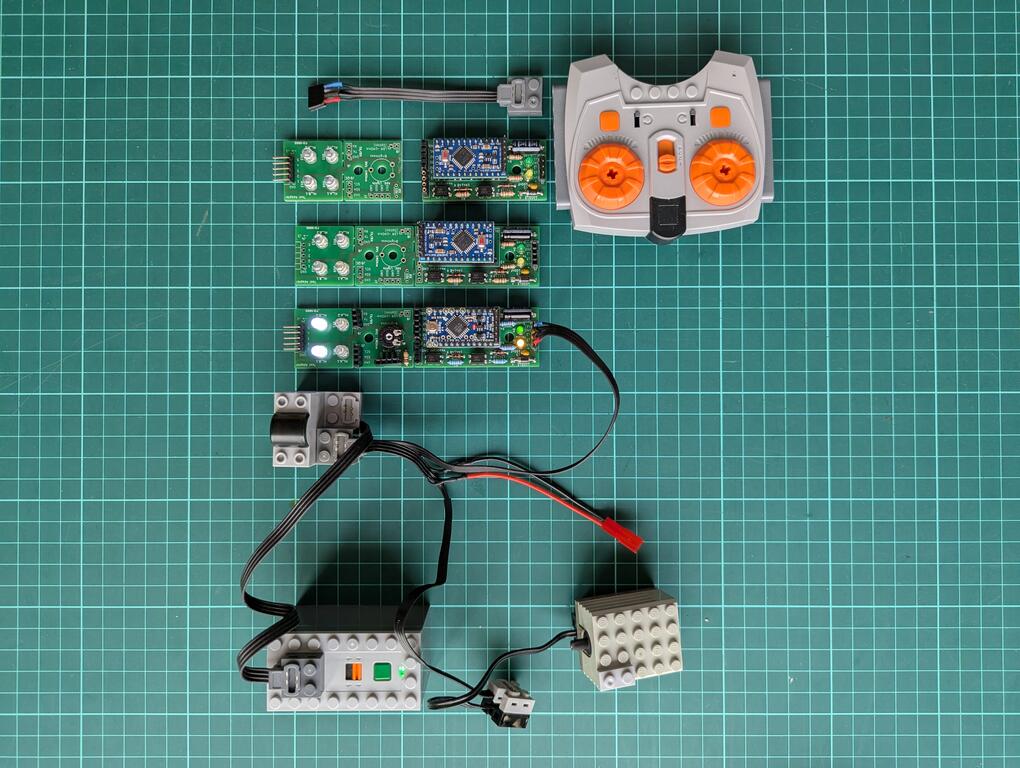
At this point in March 2026, I have a working design = hardware PCB and a working version of the software. The current version 2 (beta) hardware is built and working. Three PCBs were produced, assembled, and tested. The Arduino code was written to fit the actual HW setup, but so far it shows only the very basic function: switching lights according to direction.
I think the project is in a good beta state: real hardware exists, it works, and it is ready for practical testing. My colleague, who originally asked for this circuit for his hobby use, will show and use it in his model train club. I hope for real-life testing. This will give much better input than bench testing alone.
So the current version 2 works, but it is still beta.
Related posts
In the next blog posts I will describe:
- Hardware: schematic and PCB
- Software: detection logic and firmware
- Testing beta version 2: field reviews from the model railway guys and what to improve (open)
Outlook
Maybe there will be a version 3, depending on the input. I also hope that some of the club members will want this hardware as well, so I will design version 3, and this would also be the first DIY kit and the transition from beta to the first “official” version.