

Short overview
This is the HW description of the 電車ベクトル (Train Vector) project I described in this overview.
The main job of the hardware is to retrieve and process the signal direct from the motor, so that it can be used by the Arduino’s analogue input. The Arduino then does the magic and controls 4 LEDs (2 for each direction). The hardware will also have some additional features, so I can send out 2 more signals as a future option and also expose the I2C and TX/RX lines of the Arduino. There will also be a future option to control the brightness of the LEDs via PWM, controlled by a variable resistor or light (LDR). All this has to fit on a very small PCB, using the typical brick size.
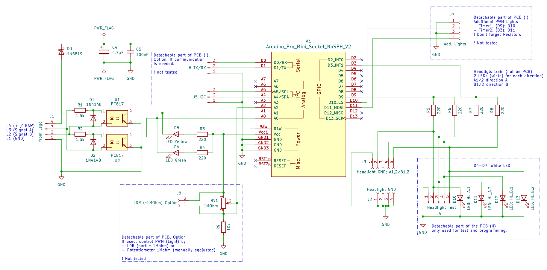
The schematic is built around these main blocks:
- input signal processing
- Arduino Pro Mini 5V as controller, also providing the 5V needed
- output section for the headlights
- test circuit
- future options
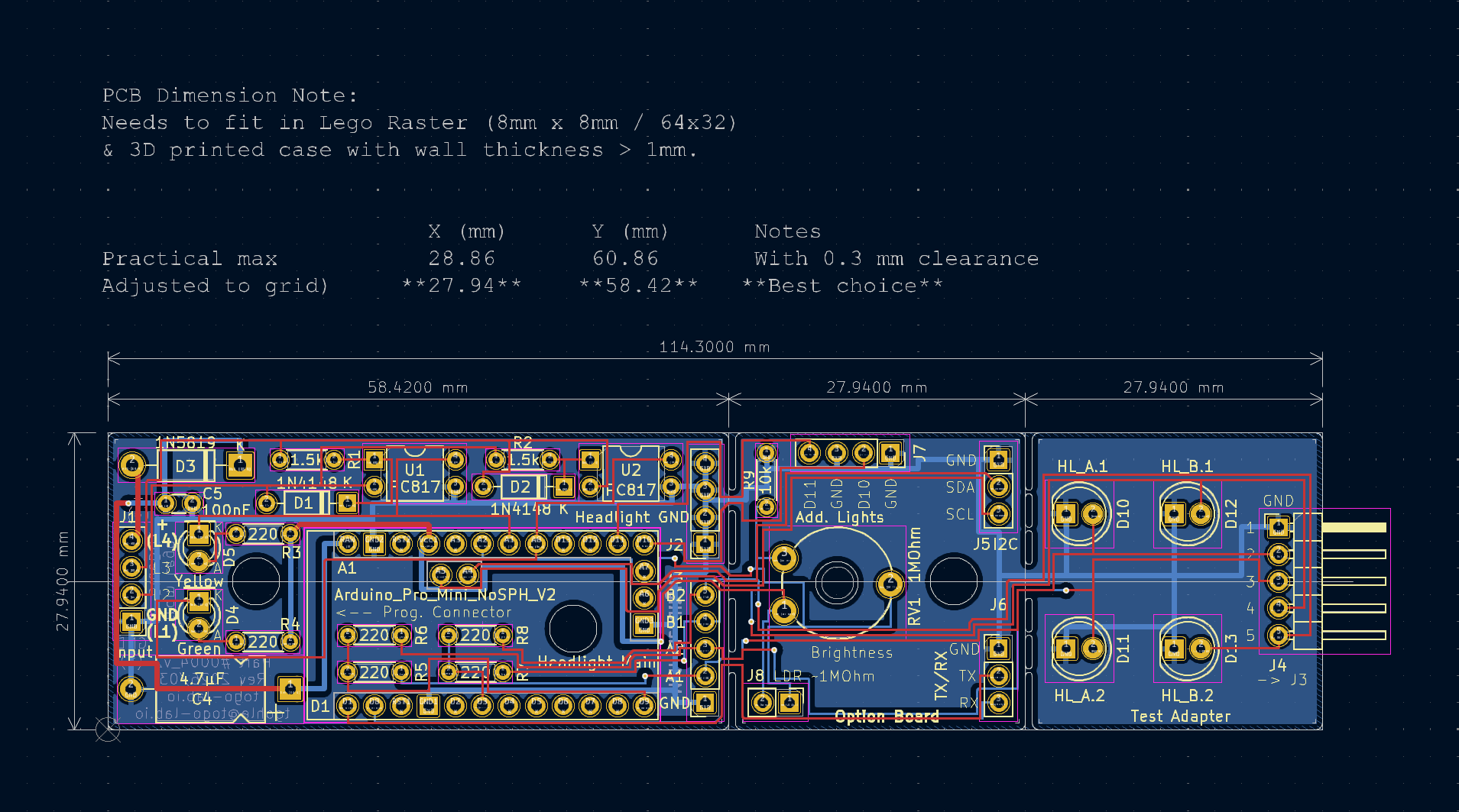
The PCB is split into 3 sections
- signal processing and controller board / section
- future options (light PWM and communication) section
- test circuit section
All details, including KiCad files, you will find in the ToGo-Lab Gitea.
Input signal processing
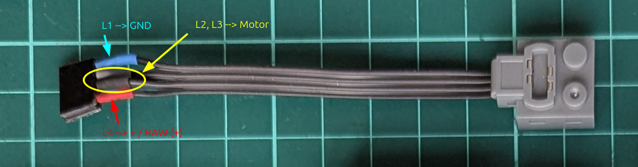
To get the signal from the brick-type motor or controller, I adapted this brick wire. In the picture you will see where the supply voltage, ground, and the motor wires are located. This connects to J1 in the schematic.
The input side reads the motor-related signals and prepares them for the controller. Because this is taken directly from the motor via J1, the signal is neither clean logic nor directly usable by the Arduino analogue inputs. It comes with switching noise, polarity changes, and inductive effects. Also, the voltage is too high to be properly handled later by the analogue inputs.
In the schematic, the parts doing this are: R1, R2, D1, D2 (input protection for the LEDs in the optocouplers) and U1, U2 = PC817 optocouplers.
To keep the controller side safer and cleaner, I used two isolated input channels with PC817 optocouplers (that was also the reason why I built a small tester for optocouplers). These optocouplers will act as rectifiers due to the polarity change (J1-3 and J1-4).
R3 and R4 together with D4 and D5 are used for pull-up, signalling (also for debugging), and of course to deliver voltage to the phototransistor in the optocoupler.
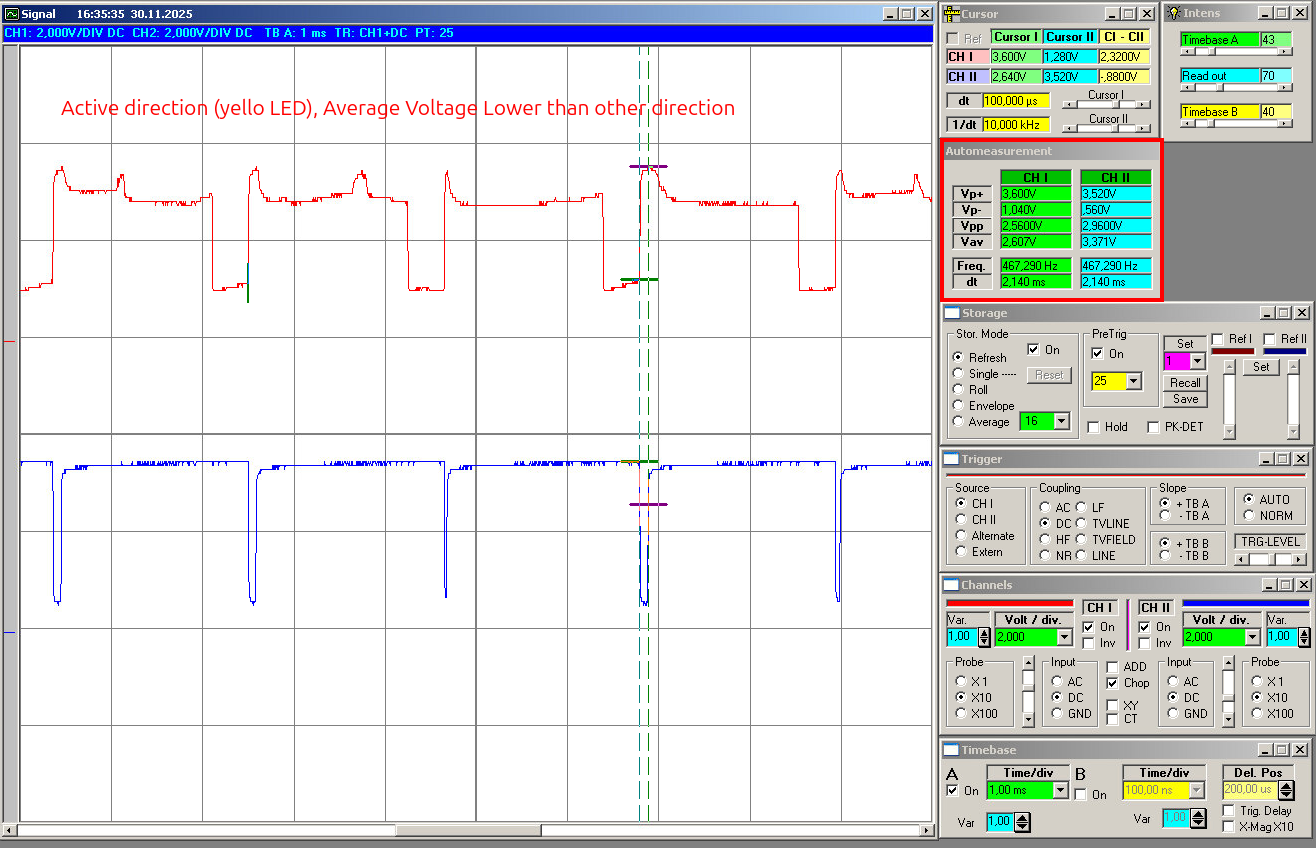
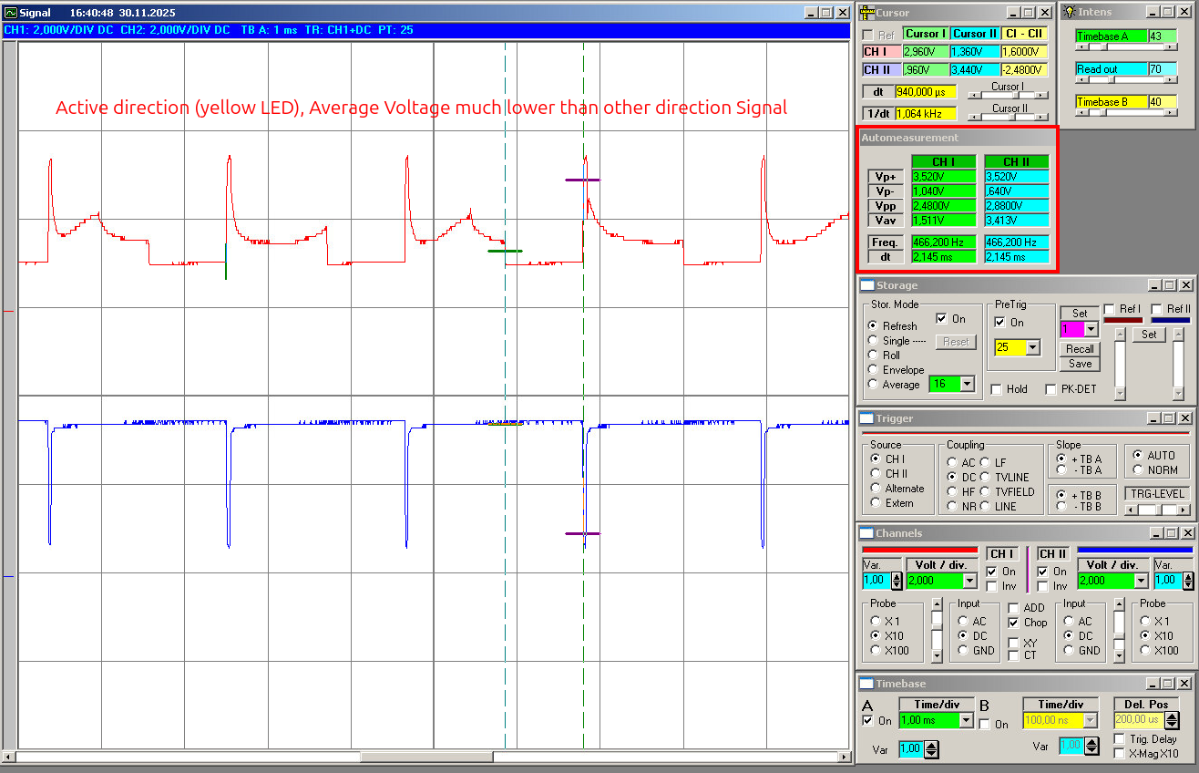
The signals will at the analoge inputs will show like this (slow, mid power, as example):
Arduino Pro Mini 5V as controller
For the controller I used an Arduino Pro Mini 5V / 16 MHz. It is small enough, I have reset logic on it, and also a power supply, so I can use the voltage directly from the remote controller. The on-board power supply will also be used to feed the optocouplers.
The Pro Mini is small, cheap, easy to replace and I understand how to program it because my programming skills are limited, I am more the HW guy, but feel free to use your own prefered µC. It is also more than powerful enough for this job and has everything needed to do analogue measurement and drive some LEDs. Another advantage is that the Pro Mini keeps the design easy to reproduce later for a DIY kit. No special programmer or unusual module is needed.
Output, future options, and test section
On the output side I used Arduino pins D3 and D9 for the two direction outputs. I used D3 and D9 because both pins support hardware PWM. The current version mainly uses them as normal outputs, but this keeps the option open for later LED dimming and other light-control functions without changing the hardware.
At the moment it is not tested; the basic function is only on/off switching of the headlights according to direction. But I wanted to keep the option open to dim the LEDs later. That could be useful for a more realistic light level, different train setups, or later expansion ideas.
Each direction drives two white LEDs in parallel, with each LED (D10, D11, D12, D13) having its own series resistor (R5, R6, R7, R8).
The future options are PWM control by resistor (RV1 and R9). You can replace RV1 with an LDR. There are also connectors for communication: I2C and TX/RX and 2 extra digital outputs to drive LEDs.
The LEDs later will be the ones in the train, so I placed the LEDs you see in the schematic on the test part of the PCB. To connect them from the mainboard I added the connectors J2 and J3.
Main PCB
The main PCB contains the complete working circuit:
- motor-side input connection
- isolated signal processing
- Arduino Pro Mini socket
- main headlight outputs
- basic support parts
This is the board that matters. If somebody only wants the core function, this is the section that needs to work. You can detach the future options part and also the test part.
The layout was done with a small footprint in mind, because the board is intended to sit inside a brick-built locomotive, where space is always limited.
Additional detachable section
There is also an additional detachable PCB section. This part is not required for the core function, but it gives room for expansion without changing the main board concept too much. In the current design this includes optional extra light outputs and an option for brightness control, for example via LDR or potentiometer. This part also expose the pins for communication, I2C and TX/RX.
Test section
I also included a small test section on the PCB. This is simply practical. For a board like this, bring-up is much easier if basic functions can be checked directly on the board before everything is installed in a locomotive. The test section helps to verify that the direction outputs behave as expected and that the board is alive before going into real use. Before installing it, you can cut this away easily.